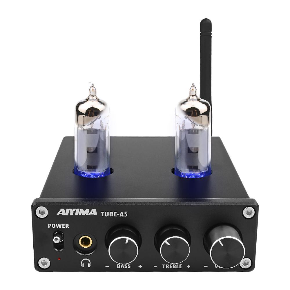
The active life of tube amp
In principle, the life of the tube amplifier is semi-permanent. Compared with the crystal amplifier, the relative life of the tube amplifier is determined by the electron tube. The theoretical life of the electron tube is not too long. Generally speaking, it is only a few thousand hours, but good tubes are common for tens of thousands of hours. For example, the kinescope of a television is a special electron tube. Of course, many audio tubes can't be compared with the life of kinescope. Generally speaking, there are transportation failures and early failures for audio tubes. The failure can be found within 1-2 months after use, or found in factory production. For a stable quality electron tube, it should be used for 2-3 hours a day. It should not be a problem to use it for 2-3 years. It is not expensive and not difficult to buy. With good after-sales service, the service life of the tube amplifier should not be a problem. After the electron tube is replaced, it can renew its vitality, just like the new machine. In fact, many antique gallbladders are now Famous products are also sold at high prices in the market. Doesn't it explain the life of the amplifier from the other side? Compared with the crystal amplifier, the high overload capacity is stronger. The crystal amplifier may be damaged in one thousandth of a second when it encounters some failures. But the amplifier can’t be damaged within a few minutes

Precautions for using tube amplifier
- Connect the load (speaker) before connecting the power supply. Never connect the signal without connecting the load or short-circuiting the load after connecting the power supply.
- The power supply should not be too high or too low. The power supply voltage should be within 5% of the specified voltage. It is best to use an AC stabilized power supply when the commercial power supply frequently exceeds this voltage value.
- When the tube is working, the temperature is high, pay attention to ventilation and heat dissipation.
- Do not spill liquid on the electronic tube during startup or just after shutdown (within 30 minutes).
In general, pay attention to the above problems in use, the amplifier can work reliably.
The combination of tube amplifier and audio-visual equipment
It is very important to use a speaker to match what kind of speakers, but it is difficult to find a collocation principle. Generally speaking, it is best to match European and American speakers with a sensitivity of over 87db such as British speakers and Italy. For example, the British HARBETH, ROGERS, SPENDOR, PROAC, B &; W, KEF, TANNOY, TDL, EPOS, MISSION, France, JMLAB, Italy, CHARIO, SOUNS FABER, some of the low-sensitivity small speakers are also particularly good for pushing the timbre, such as LS3 / 5A, PROAC TABELETTE III, and some high-sensitivity horn boxes such as: ALTLC, KLIPSCH, WESTLAKE, etc. The use of low-power single-tube Class A tube amplifiers also has a special charm. In the case of inexperience, you can find some examples of the existing collocation or the actual collocation and listen to it before confirming.

Failure and repair methods:
The failure of the amplifier is generally nothing more than the following six categories.
- The power tube is aging. You can measure the screen flow of the power tube. With a 100mA DC meter, the negative meter pen is connected to the screen electrode, the positive meter pen is connected to the output transformer, and the screen current number can be read from the meter by turning on the high voltage. Under normal bias conditions, if the measured screen current is less than the normal value, it can indicate the aging of the power tube. If the measured screen current is greater than the normal value, there may be several situations: A. The screen pressure of the power tube is too high, especially the screen voltage of the curtain is too high; B. The quality of the power tube itself is defective, the screen consumption is large, and the output The power is bound to decrease. If the screen current cannot be measured, the power tube has been damaged.
- The gate bias is abnormal. In the self-sufficient gate bias power amplifier circuit, the common gate bias faults are: A. No bias, the cause of this situation is power tube failure, no screen current, no voltage drop across the cathode resistance, cathode bypass capacitor was broken down, etc. B. The bias voltage is small, because the power tube is aging or the screen pressure is low. C. The bias voltage is high because of increased screen voltage, especially increased screen current, increased screen current, increased resistance of the cathode, leakage or breakdown of the gate cross-connect capacitor, and a positive voltage applied to the gate. Species. In addition, the open cathode resistance will also increase the bias voltage. At this time, the screen current is very small, and there is parasitic oscillation in the line.
- The output transformer is partially short-circuited. It will cause the screen flow to increase, and the screen will become red, the output will decrease and the distortion will increase. If it is a primary partial short circuit, the output voltage will not decrease under no load. When the load is connected or the load is very light, as long as the grid excitation voltage reaches the rated value, all the power tubes will be red. This is a typical phenomenon. When checking whether the output transformer primary is partially short-circuited, the primary and secondary wiring of the output transformer can be completely disconnected from the circuit, and the 220V mains power is sent from the primary end. The voltage of the two primary ends and the B + center head is measured with a multimeter. Normally, the voltage of the two terminals is equal. When there is a partial short circuit, the voltage at one terminal is lower than the voltage at the other terminal. If the 220V mains power is connected and the fuse is burned out immediately, it means that the local short circuit is very serious and the output transformer must be replaced. Before checking the output transformer for short-circuit faults, first check whether the high-frequency suppression circuit and negative feedback circuit components connected in parallel on the secondary are degraded, failed, and broken, and then check between the secondary line and the iron core Whether there is a breakdown short circuit.
- The driving level excitation voltage (or power) is insufficient. The excitation voltage (or power) of the power tube grid is not enough, no matter how normal the working state of the power tube is, it still cannot have a rated power output.
- Multi-tube parallel push-pull operation, in which one or several tubes' screen suppression resistance or grid suppression resistance is open, at this time, not only the distortion is large, but also the output power is small.
- The cathode bypass capacitor of the self-sufficient gate bias fails to form an open circuit, which generates negative current feedback. For some amplifiers, it may affect the output power.

There are two cases of high voltage failure: one is that the fuse blows immediately when the power is turned on, and the other is that the fuse suddenly blows the fuse during the work process and cuts off the high voltage power supply. Disconnect the high voltage B + of the center head of the output transformer of the amplifier and the high voltage power supply, and then turn on the high voltage. If the fuse is still blown or the high voltage cannot be started at this time, the fault is not in the power amplifier circuit but in the power circuit; after the connection, the high voltage can be started, then it can be sure that the fault is in the power amplification stage. If the high-voltage power supply of the power amplifier stage cannot be added, it should be checked from the following aspects:
- Observe or test whether the electrodes inside the power tube are connected.
- Check whether the output transformer is short-circuited. It is common that the primary or secondary coils are short-circuited.
- The load is too heavy or the load is short-circuited. Excessive load or short circuit can cause the screen current to increase and overload, blow the fuse or not apply high voltage.
When the amplifier exhibits parasitic oscillation sounds such as "sizzling" high-frequency oscillation and "flapping" low-frequency oscillation, the screen consumption will increase at a lighter level, the screen will become reddish, and the output will decrease. There are several reasons for parasitic oscillations:
- The components such as negative feedback resistance are deteriorated or damaged.
- Bypass or breakdown of the bypass capacitor in parallel with the secondary of the output transformer causes high frequency oscillation.
- Multi-tube parallel push-pull working screen, grid resistance damage or deterioration can easily cause oscillation. Replacing the gate resistance, never use a wire-wound resistor because its inductance will cause oscillation.
- The power tube, especially the high transconductance power tube and the components in the oscillation suppression circuit change parameters after a long time, and it is also easy to produce oscillation.
-
The power supply voltage is too high. Because the power supply voltage is too high, the normal working state of the power tube is destroyed, and it can also cause oscillation.

When the amplifier is working normally, if the screen is extremely red in a bright environment, it is abnormal. The cause of the redness of the screen may be:
- Excessive load causes excessive screen flow. This phenomenon is relatively common, mainly due to improper speaker impedance matching, or short circuit of the external line, or partial short circuit of the primary coil of the output transformer.
- The negative gate bias is reduced, or there is no negative gate bias, or a positive gate bias occurs. The reason for the negative gate bias voltage reduction may be: the failure of the negative bias power supply filter capacitor or the reduced capacity; the center slider of the voltage-dividing load potentiometer is adjusted too low; the rectifier aging; the partial local short circuit of the bias power transformer secondary; the self-sufficient grid bias voltage The cathode bypass capacitor has serious leakage; the primary and secondary (or coupling capacitor) of the input transformer have slight leakage and other problems. The reasons for no negative gate bias voltage may be: the center tap of the input transformer is open; the filter capacitor of the bias power supply is short-circuited; and the bias load resistance is damaged. The rectifier or the bias voltage transformer is damaged; the self-sufficient negative grid bias cathode bypass capacitor breaks down; the gate resistance or the input transformer secondary circuit is broken; the base is damaged, so that the gate pin is separated from the base.
- The screen pressure or curtain grid pressure of the back-stage power tube increases, which increases the screen flow and makes the screen extremely red. The reason for the increase in screen voltage may be: A. The primary coil of the high-voltage power transformer is partially short-circuited, causing the AC voltage of the secondary high-voltage coil to increase; the output DC voltage after rectification increases; B. Bleed resistance, open circuit, output voltage rise. C. The filter choke coil is partially short-circuited, the inductance is reduced, the voltage drop is reduced, and the output voltage is increased. The voltage of the curtain grid rises (refers to the machine that uses beam tetrode and pentode as the power amplification stage), the ability of absorbing electrons is enhanced, the screen current is increased, and the screen electrode is red.
- Ultra-audio or high-frequency parasitic oscillations cause the screen to become extremely red. These two parasitic vibration oscillations are caused by the positive feedback of the total parasitic capacitance of the subsequent stage. An effective method of judgment is that when the screen is red, the load impedance is replaced by a resistance of about 1/20 of the output power of the amplifier, and the resistance is equal to the output impedance. The signal is not sent after starting up. After a few minutes, if the hand touches the resistor and feels hot, then there is high-frequency parasitic oscillation.
- The push-pull tube ages, destroying the push-pull balance, causing the screen to glow red. In push-pull power amplifiers, especially in parallel push-pull (such as 150W amplifiers generally use two KT-88 tubes in parallel), one of the tubes is aging, the internal resistance increases and the screen current is reduced, and there is no burden of the aging tube. Heavy, the screen flow increases and the screen is extremely red.
- One side of the primary coil of the output transformer is partially short-circuited, which destroys the push-pull balance, increases the screen current on that side, and makes the screen extremely red.
- The input signal is too large, causing the output current and voltage to exceed the rated value, causing the screen to glow red.
- Some amplifiers are not designed properly. Due to screen pressure, curtain grid voltage, filament voltage is too high, or negative grid bias voltage is too small, static screen flow is too large, even when static, it will make the screen extremely red.
Distortion
The so-called distortion refers to the difference between the output of the amplifier and the input waveform is too large, the sound amplified by the amplifier is different from the original input sound. The main reasons are as follows:
- The push-pull power tube or push-push tube has an aging (or damage), so that the gain of the two tubes is different, or the primary side of the output transformer (or the secondary side of the input transformer) is partially short-circuited or open circuit; The change of the extreme anti-vibration resistance will also destroy the push-pull balance and cause distortion.
- Some amplifiers' push-pull and preamp are coupled with resistance-capacitance, and distortion occurs when the coupling capacitor on one side changes in value (capacity becomes smaller, failure, leakage, etc.). If the capacitor leaks, it will also make the negative gate bias voltage of the next-stage electron tube smaller, or even become a positive voltage, resulting in grid current, causing distortion.
- If the fixed negative gate bias voltage is too high or too low, the working point of the tube changes, or the input signal is too large, etc., can make the tube work in the non-linear part, causing distortion. The power tubes of small power amplifiers generally work in AB1 (or Class A) push-pull amplification. If the peak value of the input signal voltage is greater than the negative gate bias, the gate current will appear in the power tube. Large, so it is easy to cause distortion.
- In amplifiers above mid-power, the power tubes generally work in AB2 (or B) push-pull amplifiers. If the output power of the driving stage is insufficient or the internal resistance is too large due to the aging of the driving tube, it will cause distortion. In order to obtain a stable output voltage, the booster stage must use a tube with a small internal resistance and invert the phase with a step-down transformer.
- The load resistance, cathode resistance or curtain grid resistance of the screen electrode changes value, so that the working point of the electron tube changes and works in the nonlinear region, causing distortion. The gate resistance is broken, causing blocking distortion. At the same time, the load impedance is too light or too heavy, so that the output impedance of the tube does not match, causing distortion or light sound.
- The power supply voltage is unstable or too high or too low, which will change the working point of the electronic tubes at all levels, causing distortion.
Hum
Generally speaking, because the voltage amplification of the subsequent stage is not large, the hum caused by the failure of the power amplifier stage is not very obvious, but there are several kinds of failures that can produce obvious hum.
- Short circuit or leakage of the internal cathode and cathode poles of the power tube, the cathode and the filament are short-circuited, and the filament power transformer is not well grounded.
- Poor filtering of fixed bias.
- Promote the leakage between the primary and secondary of the transformer, or the leakage of the grid cross-connect capacitor to make the grid positive.
- Poor grounding of the whole machine. In particular, the duct welding and filament-powered amplifiers have high requirements for grounding. During the debugging process, each grounding point must be tried continuously to obtain the best signal-to-noise ratio. In addition, the resistance of the grounding point should be as small as possible.

Focus on Audio


Leave a comment
This site is protected by hCaptcha and the hCaptcha Privacy Policy and Terms of Service apply.